Analyzing signal integrity with open source libraries
I just returned from this year’s C++ Now (formerly BoostCon) conference, where one of my favorite presentations was from a couple of students at University of Potsdam, who have released an open-source numeric integration tool for ordinary differential equations, called odeint. Their library handles any differential equation of one independent variable (say, “t”) that can be written this way:
\[\begin{align*} \frac{d\boldsymbol{X}}{dt}& = f(\boldsymbol{X}, t) \end{align*}\]where the state variable X may be a vector. Higher-order (second, third, etc.) derivatives are handled by modeling derivatives as state variables themselves.
Of course as I was watching the presentation I immediately thought of circuits, and in particular the linear circuits that arise when modeling interconnect. Optimizing routing for speed, signal integrity, etc. is a thorny problem and in the systems I’m aware of is usually handled by rules of thumb produced from repeated Spice runs on your process technology. Being able to run an accurate simulation of a routing configuration directly in your tools would be incredibly empowering. So I decided to give it a try.
My first test case was a basic damped RLC circuit with a step (voltage) input. I needed three state variables for this: the input voltage, the inductor current, and the output voltage. KCL on the output node gave me the only interesting one of the three dX/dt equations, and the output (viewed in gnuplot) looked great. I decided to try a signal coupling scenario next.
The coupling scenario was more complex than the RLC circuit, but even so most of the dX/dt equations came directly from KCL. The tricky part came when considering the nodes on either side of the coupling capacitor connecting the aggressor and victim wires. The current through this capacitor is a function of the difference in the derivatives of the nodes on either end; you end up with two equations (KCL on the nodes) in two unknowns (the two node derivatives). I substituted manually and got the simulation running:
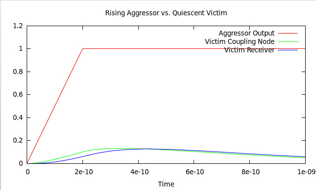
To check accuracy I built the same circuit in NGSpice and compared results from .MEASURE statements to raw data extracted from my simulation and I have a pretty good match (within 0.5%) on delay and an excellent match (within 0.1%) on the victim receiver voltage. The source code is here and my NGSpice deck is here.
The next logical step would be to take an arbitrary RC network, apply KCL, rearrange the resulting equations to isolate dX/dt, and thus automatically produce a model suitable for use with odeint. I don’t currently know how to do this, but I’ve a feeling matrix algorithms are involved :)